Standard is the default — start there unless you have data telling you otherwise. The offset compensates
for your printer + resin's dimensional drift. Pick one offset and use it on both the calibrator and
the attachment library — they must match. Plates have no offset.
TIGHT
Negative drift
STANDARD
Default · most printers
LOOSE
Positive drift
RULE
The calibrator and the attachment library must share the same offset. Plates have no offset — only the calibrator and attachments do. Mixing offsets causes seating errors.
Phase 01 · 02
Print fitting_TEST first
Slice and print fitting_TEST_READY-TO-PRINT.stl. Same printer, same resin, same settings
you'll use for every production model from now on. The fitting_TEST is small and fast — it proves the
offset before you burn the full calibrator.
CRITICAL
Use exactly the printer + resin + settings you will use for every future production model. Anything else means recalibration.
Phase 01 · 03
Test the fit on the upper plate
Clean and cure the fitting_TEST. Try seating it on the upper plate.
Too tight to seat → switch to Loose.
Sloppy → switch to Tight.
Firm with no slop → Standard is correct.
GUIDANCE
Tight = printer prints undersized (positive offset compensates). Loose = printer prints oversized. Most printers are Standard.
Phase 01 · 04
Slice and print the full calibrator
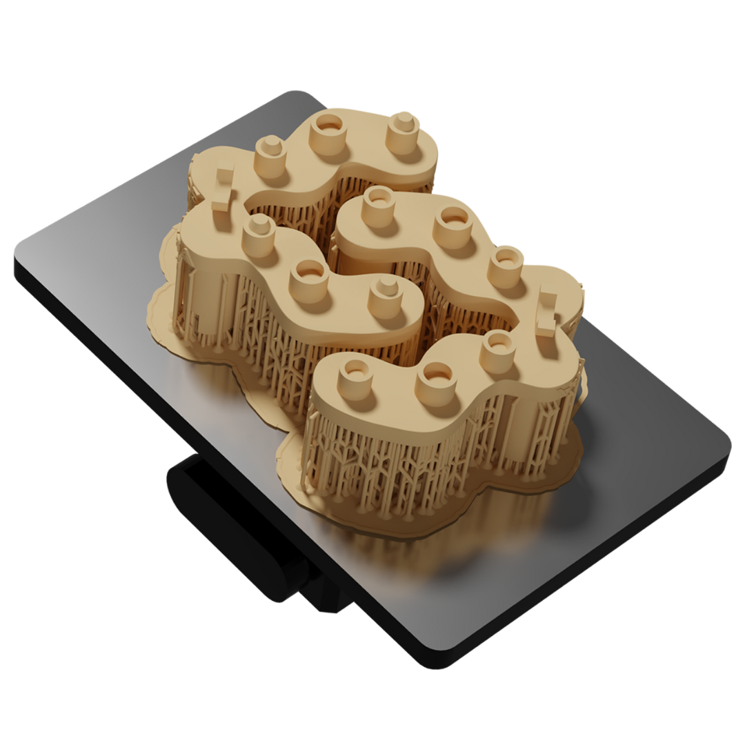
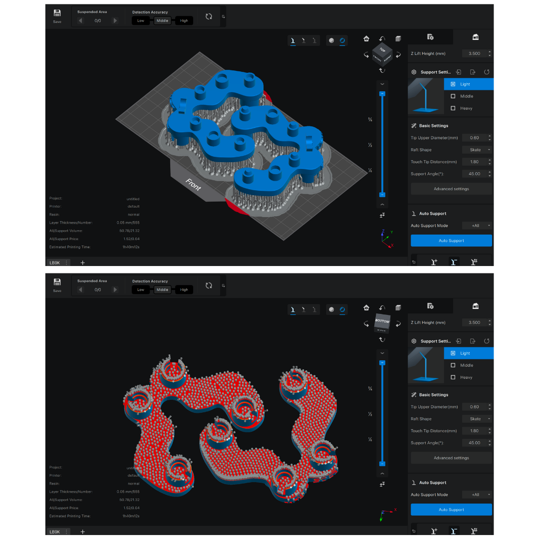
Once the offset is confirmed, load the full calibrator into your slicer. Same printer, same resin,
same settings as the fitting_TEST. Two ways to handle supports:
Fast path — use the *_READY-TO-PRINT.stl in your matching offset
folder. Pre-supported, drop straight in. Custom path — use the bare (non-supported) STL from the same ZIP and place your
own supports. Reference the ready-to-print file to see where and how the
pre-supports are placed.
Both files are free in the same ZIP. If you have a slicer profile you trust, the
bare STL gives you full control. The pre-supported variant is just a known-good reference.
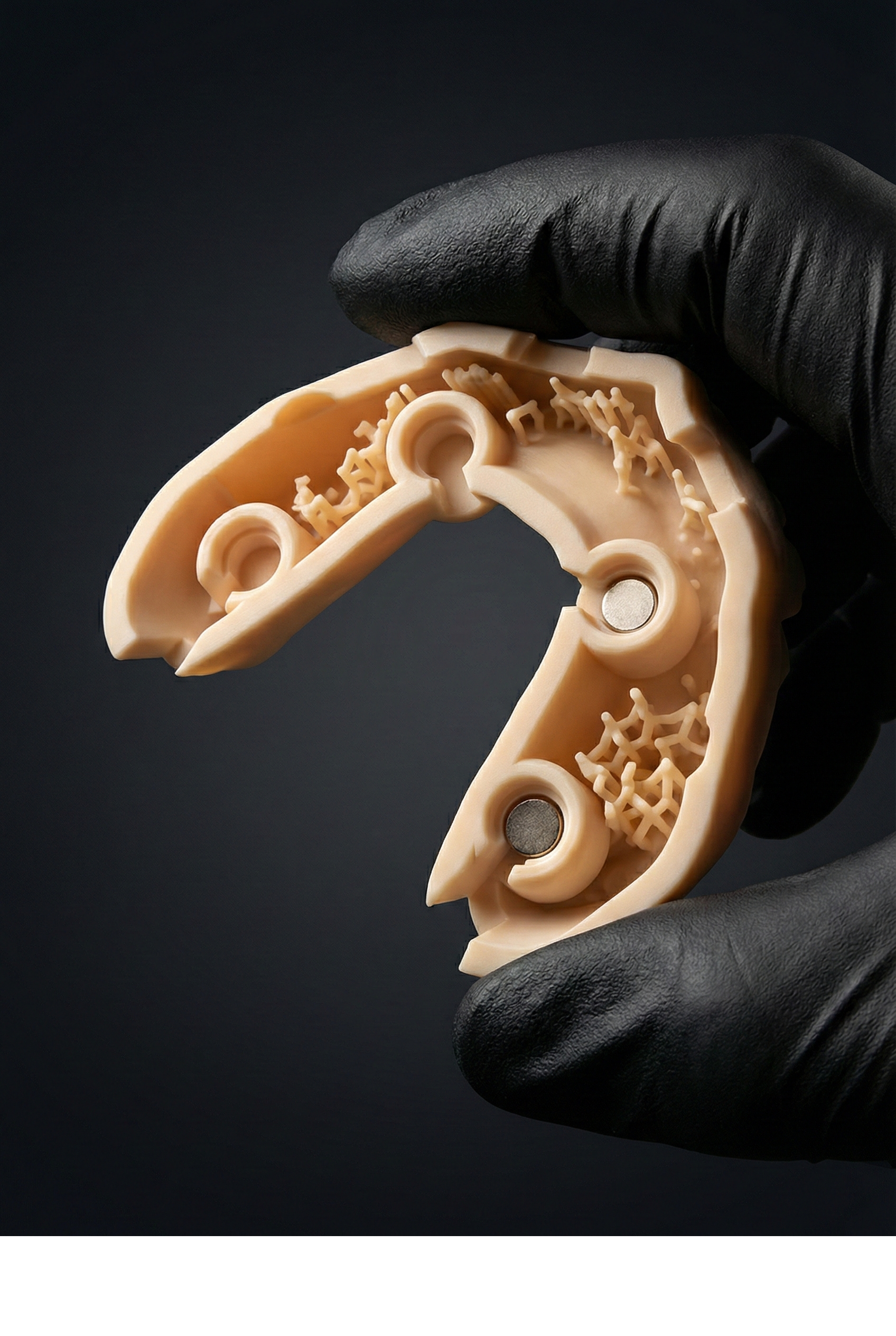
NEVER ON THE MAGNETS
Do not place supports on the internal magnet reference surfaces. Anywhere else is fine.
Phase 01 · 05
Post-process and inspect
Remove supports. Wash and cure exactly as you would a working dental model. Inspect the magnet
reference surfaces under raking light — they must be clean and flat. Any residue or distortion here
corrupts the calibration permanently.
INSPECT
Magnet reference surfaces must be clean and flat. Re-print if any are damaged or under-cured.
Phase 02 · Direct · 01
Mount the upper plate
Lock the upper plate to the articulator's native split-cast or screw interface. The brand-specific
upper plate is keyed to your articulator (Artex / SAM / Asa) — it should seat with no force.
Phase 02 · Direct · 02
Position the lower bowl
Drop the lower bowl onto the lower arm of the articulator. It seats on the standard mounting surface —
no plaster on Direct kits.
Phase 02 · Direct · 03
Fine-tune calibration · bond the lower plate to the bowl
This is where the calibration is locked in. Apply plaster (or silicone,
90 Shore A) inside the concavity of the lower plate. Magnetise the calibrator onto the
upper plate so it bridges upper to lower, then close the bowl onto the lower plate. The material
flows into the cavity; once cured, bowl and lower plate become a single piece. The plaster /
silicone is incorporated inside the plate and won't be visible from outside.
PLASTER vs SILICONE
Plaster is the default — strongest bond.
Ultra: silicone (90 Shore A) is fine — small cavity, less material needed.
Light: the cavity is larger; silicone fills it but with less stability than
plaster — use plaster on Light unless you have a reason.
Phase 02 · Direct · 04
Confirm calibration · lock the articulator
With both plates installed and the calibrator seated, the articulator is calibrated. Remove the
calibrator — the upper plate now holds the reference for every production model that follows. No
remount, no plaster, no recalibration between cases.
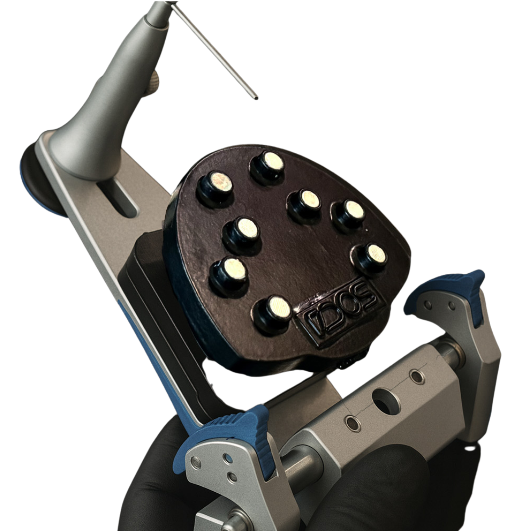
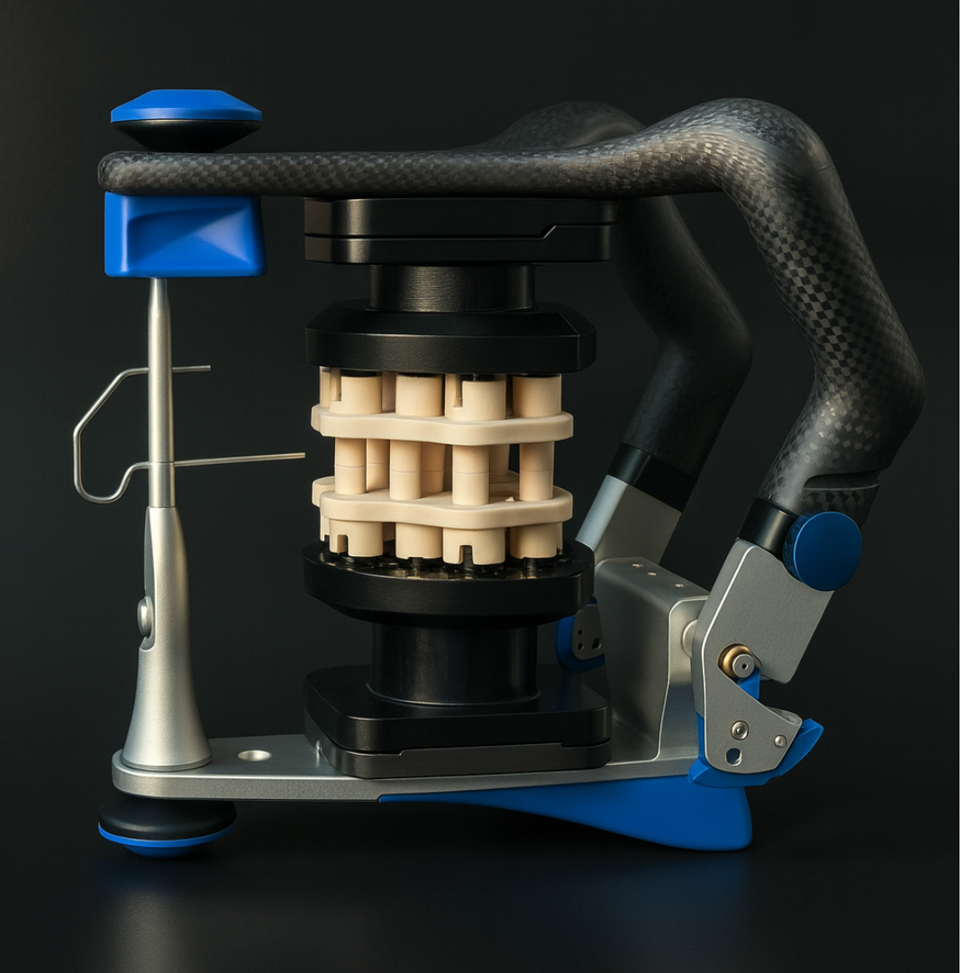
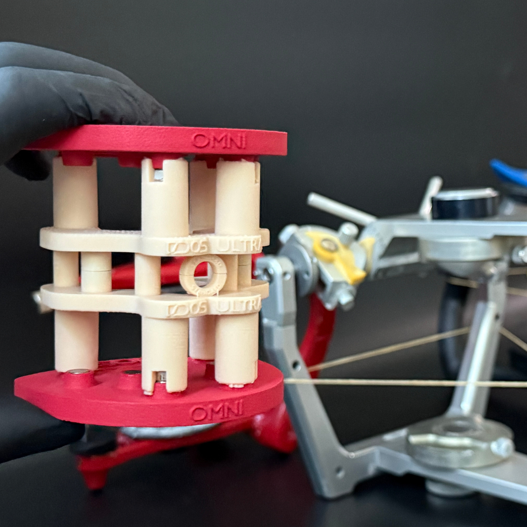
Phase 02 · Flex · 01
Stack plates with calibrator between
Magnetise the calibrator between the upper and lower Flex plates. This is the assembly you'll plaster
onto the articulator — the calibrator holds both plates at the correct vertical reference.
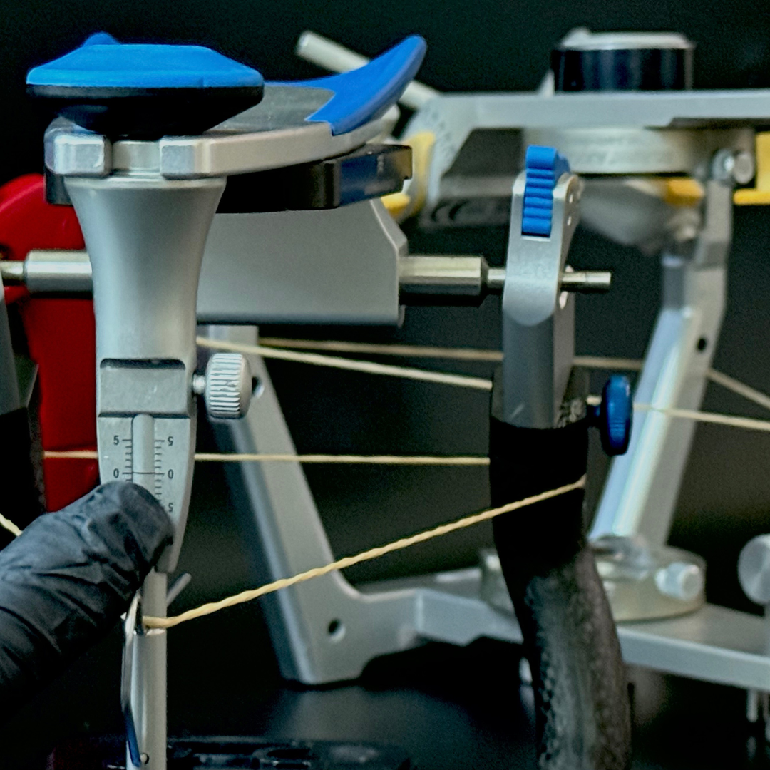
Phase 02 · Flex · 02
Verify the articulator pin is at zero
Pin at zero, condyles locked. Anything else and the calibrated reference will be biased — Flex
relies on the articulator's own zero state at install time.
CRITICAL
Pin at zero before plaster touches the plates. Once cured, the position is locked permanently.
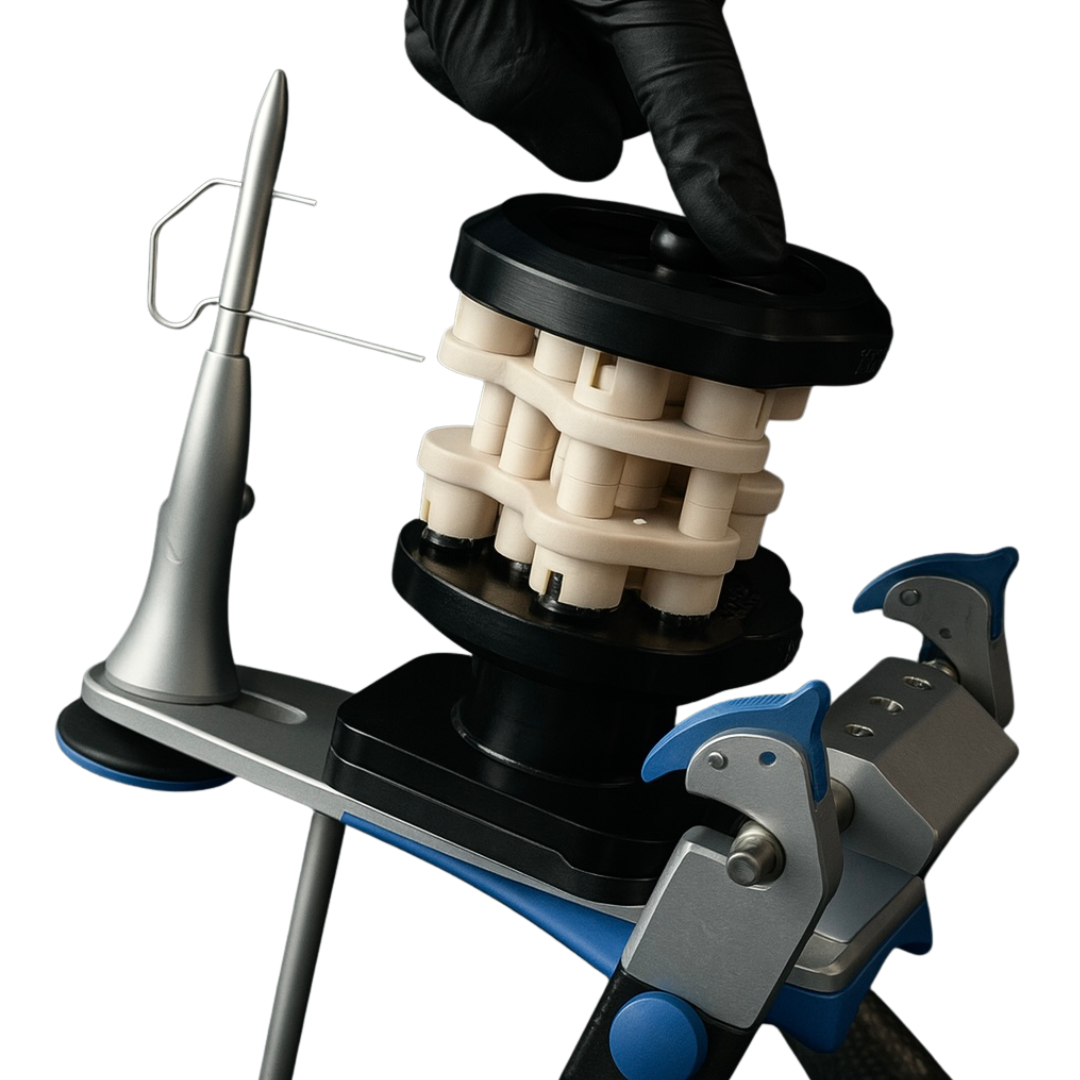
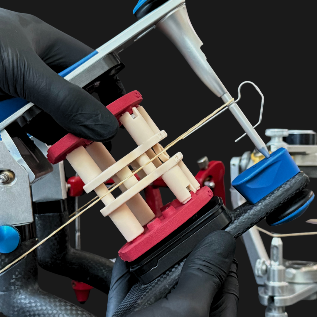
Phase 02 · Flex · 03
Stretch the Bonwill elastic across the upper plate
The elastic is the occlusal-plane reference. Adjust the assembly until the upper plate sits parallel
to the elastic — that's the calibrated occlusal plane for your articulator.
Phase 02 · Flex · 04
Plaster-fix the plates · let cure
With pin at zero and the elastic confirming the plane, plaster the upper and lower plates onto the
articulator arms. Hold position until set. Once cured, the Flex install is permanent and the
calibrator can be removed — the magnetic reference stays.
Need the full installation walkthrough? Click the ▶ WATCH INSTALLATION button in the top-right of the workspace — it covers calibrator printing and plate installation end-to-end.
Phase 03 · Exocad · 01
Download plate + matched attachment library
The plate library (DACOS_Omni_Plates.zip) is shared across kits. The attachment library
is tier + offset specific — download the one matching your kit (Light or Ultra) and the offset you
confirmed in Phase 01 (Tight / Standard / Loose). Both are in the dock below.
OFFSET MUST MATCH
The attachment library offset must match the offset on your printed calibrator. Mixing offsets causes seating errors at print time.
Restart Exocad after copying so the libraries are picked up. Confirm both appear in Model Creator's
dropdowns before moving to step 03.
Phase 03 · Exocad · 03
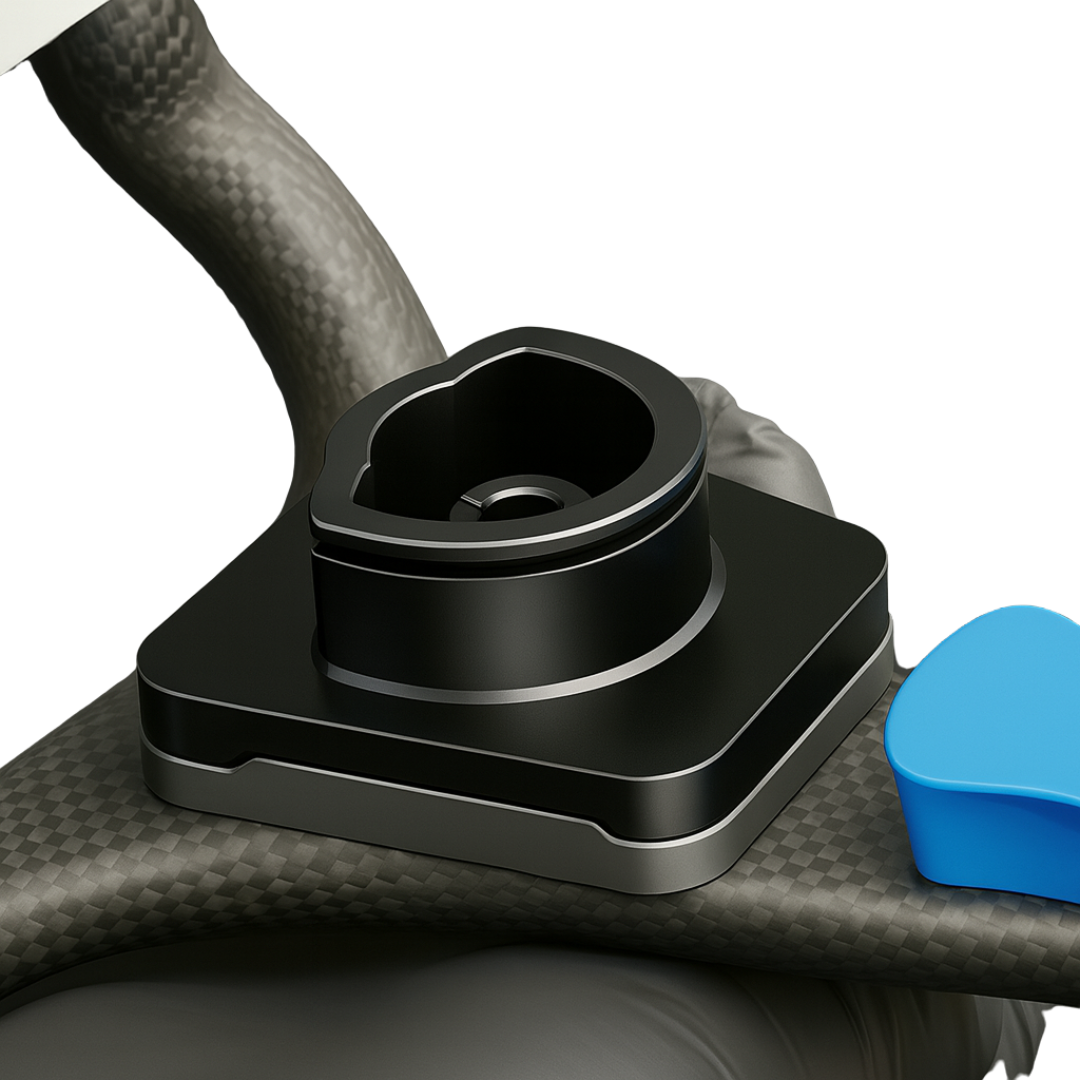
Use the libraries on every production model
Open Model Creator → pick the DACOS plate only to set model height → place the four DACOS
attachments on the underside. Export the STL. Print on the calibrated printer + resin. Insert magnets
via GlueJet or GlueJet Spider. Snap onto the upper plate. Done.
PLATELESS WORKFLOW
The DACOS plate exists only to set model height — it is not a model base. If you prefer flat
gingiva or cut-out dies, use Exocad's plateless model workflow with flat gingiva
or cut-out dies, then set model height to the minimum required for the attachments below.
Minimum model height per kit:
Light 40 mm ·
Ultra 55 mm ·
Ultra Extended 40 mm
This is the daily cycle. No remount. No recalibration. No plaster. The magnets enforce the calibrated position every time.
WalkthroughDACOS Omni installation — covers calibrator printing (Phase 01) and plate installation (Phase 02). CAD library setup is documented in Phase 03.